What may sound like a contradiction in itself is the title of a bi-annual competition, happening in Cologne in 2017. This 16th edition attracted over 1’000 participating students in 119 teams. While the regatta is also a sporting event, a big scientific interest is on the innovations in concrete construction methods. Prices are awarded therefore not only for the fastest but also for the lightest canoe and the most advanced technology.
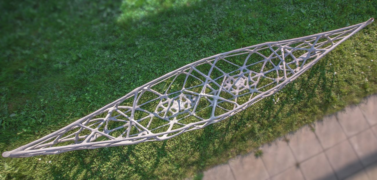
Our contribution was the result of a bachelor thesis project in collaboration with PCBM, the chair for physical chemistry of building materials. The four-meter-long canoe, dubbed skelETHon, consisted of a truss-like tubular skeleton made of ultra-high-performance fiber-reinforced concrete (UHPFRC), covered with an only a few millimeters thick skin of textile, infiltrated with a concrete mix especially developed for this application by our collaboration partners. More details about the regatta, the concrete or the fabrication of the less than a millimeter thick 3D-printed formwork can be found in supplementary publications. The main focus here lays on the design and generation of the tubular skeleton geometry.
The first design step consisted of discretizing the volume of a traditional wood and canvas canoe into predominantly cubic finite elements of ±15mm edge length. The TOSCA engine of the professional software package SIMULIA ABAQUS was used to perform a topology optimization under two different load cases:

- the floating situation in water: self-weight G and live point loads from two canoeists P1 and P2 and a distributed support force provided by the hydrostatic pressure Hp
- the transport situation on land: self-weight G and two point supports T1 and T2 carrying the canoe
The optimization target was to reduce the material to a 15% fraction of the initial volume while minimizing the strain energy in each node. The result after many iterations is a branching structure of ribs and tubes, some explicitly present, others only indicated by a gradient of porosity, that are supposed to guide the forces through the volume in an ideal way. The strain in each node is shown by the hue level in the picture above. The next step was to retrace the principle axes of these branches of crystallized denser conglomerates of nodes, to create a clean curve network cage. Following this stage, the curve network can be adjusted slightly to account for constraints of the fabrication process (e.g. maximum overhang for 3D printing) or additional axes can be introduced in low density regions to limit the field size to the maximum span of the waterproofing skin.
The next step is where volumetric modelling comes into play. The thickening of axial line skeletons can be done in different ways. A common approach with BRep modelling is to create polygonal profiles perpendicular to each edge of a node, offset by a certain distance from the node centre, combine all the points on these polygons with a convex hull, connect the two polygons on either side of an edge with quad faces and combine all these faces in a polygonal mesh. If needed, this first raw mesh can be further smoothened by iterative subdivisions. This method can be very fast and efficient, but it requires edges to meet exactly in one point (no T-junctions) and it is susceptible to too many edges meeting in one node or at too acute an angle. Potential changes in topology induced by increasing tube diameters or nodes being too close together cannot be handled unless these exceptions are caught explicitly.

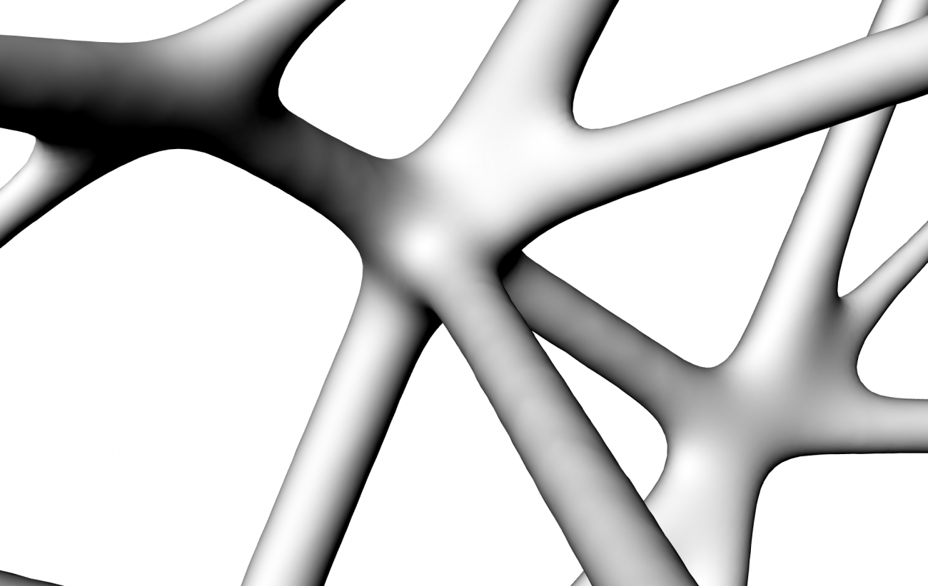
We place capsules (cylinders two spheres on either end) defined by distance functions along each axis segment and calculate the Boolean union of all of them. Depending on the amount of stress each tube has to take they are assigned to different groups of 15, 25 and 35mm diameter respectively. These diameters are based on previous rheological studies with 3D printed formwork and the same mix of concrete. The entire bounding box of the canoe is then sampled with a dense orthogonal grid of voxels. This allows us to apply a 3D Gaussian convolution kernel to smoothen the sharp creases at the pipe intersections which is beneficial not only for the fabricability but also for both the force and the concrete flow during the casting process. The result of the described process for two nodes of degree six is shown above. The filleting region is automatically distanced further away from the node center if two tubes meet at an acute angle. The method is very robust and can also handle any changes in topology very well. If e.g. the tubes around a small triangular patch in the network need to be thickened because of an increased stress level, the opening vanishes (genus number decreases by 1) without causing any self-intersections or inconsistencies.
From the final scalar field, an isosurface was generated and the typically unbalanced mesh resulting from the marching cubes algorithm rebuilt with approximately equilateral triangles. On the outwards facing side, a pyramidal subdivision was applied to increase friction and therefore adhesion between skeleton and skin (see header image). Constraints such as available build volume and surface orientation, but also for risk reduction by parallelizing the production process, the entire tubular structure was split up in 84 parts, 3D-printed in translucent PLA on FDM-printers and welded together into one continuous formwork. The concrete was then cast through inlets distributed along the z-axis, starting from the bottom and the formwork’s translucency allowed for a permanent inspection of fill level and potential air bubbles trapped. After the removal of the formwork, the four-meter-long concrete skeleton was ready to be covered with the textile skin and coated with the cement glue.

This design won us the first prize for the best design innovation.
- Bachelor Thesis Students: Moritz Studer, Oliver Wach and Katharina Ziegler
- Tutors: Andrei Jipa, Mathias Bernhard (DBT), Nicolas Ruffray, Lex Reiter (PCBM)
DBT project page: dbt.arch.ethz.ch/project/concrete-canoe

